Buck-converter with recycled discrete components
SAGI Universe
July 2021
1.Introduction
Often, there is a need to convert an higher, variable DC voltage to a lower, fixed one. For example, transform a solar panel voltage to a fixed 5 V, or transform a 9V battery voltage to a fixed 3.3 V.
This could be done with a series regulator (for example the LM74XX family) but it would involve (especially for an high input voltage range) a very large power loss.
A better way, is to use a switched DC/DC converter, normally called buck-converter (on the contrary, a boost converter converts from a low DC voltage to an higher DC voltage).
There are plenty of circuits available, the majority of them based on dedicated integrated circuits.
However, it is possible to build simpler version circuit using recycled discrete components, which could be an emergency solution in case no other components are available.
2. The buck converter
A simple explanation of the way of operation of this circuit topology can be found on Wikipedia (ref.1) and on hundreds of other sites.
The basic circuit is shown in the next figure:
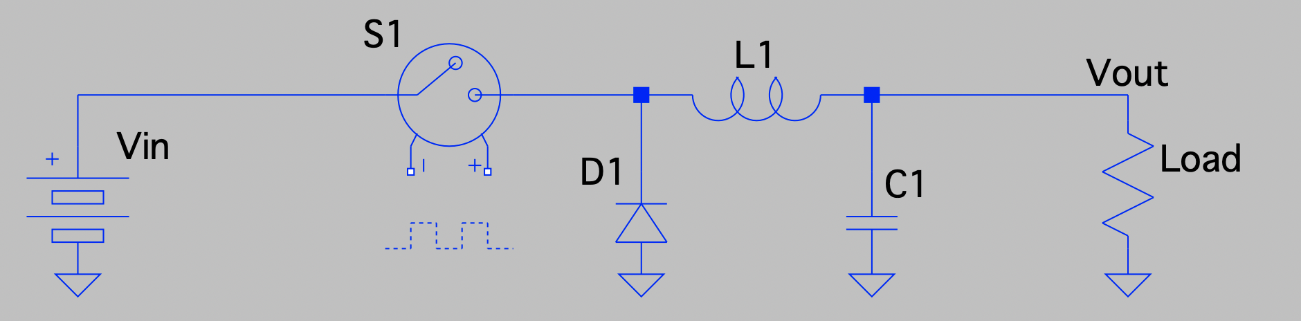
Figure 1 - Buck-converter concept
It consists of an input voltage source, a controlled switch, a diode, an inductor, a capacitor and a load.
In a simple way, the circuits works like this:
· When the switch S1 is closed a current flows from the input voltage source Vin through the inductor L1 to the load. The output voltage Vout is equal to Vin times the S1 control voltage duty cycle.
· When the switch S1 is open, the magnetic energy in the inductor L1 maintains this current through the diode D1.
· The capacitor C1 filters the AC component of this current so that the Vout is a DC voltage.
3. Implementation with discrete components
The switch S1 can be implemented with either a bipolar transistor or a MOSFET and the controlling voltage can be generated with an astable multivibrator.
However, with this simple implementation when the input voltage changes, also the output voltage changes. Therefore, to a stable voltage, the output voltage can be sampled using a Zener diode (with a voltage equal to the desired output voltage) and the duty cycle of the multivibrator is changed to maintain the output voltage constant.
This can be seen in the final circuits of figure 2 (BJT implementation) and figure 3 (MOSFET implementation).

Figure 2 - Buck converter final circuit base on a BJT (NPN)
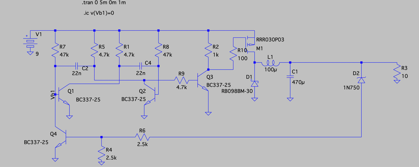
Figure 3 - Final circuit based on a MOSFET (P-channel)
The feedback loop can be tuned replacing the R4/R6 resistors with a 5KOhm trimmer. In this way, you can adjust the output voltage around the voltage set by the Zener diode D2 (in this case a 4.7 V Zener).
Concerning the diode D1, in the circuit we used a Schottky diode to reduce as much as possible the insertion voltage. However, the circuit would work with also a normal diode.
Transistor choice is also very flexible, any low power NPN transistor would do.
Of course, the choice of the switch element depends on the current you want to supply to the load. However, also in this case the choice is pretty large.
For the inductor L1, the choice of the inductance is also not critical. You should experiment with what you have available.
You can also experiment with the astable multivibrator frequency, by changing the C2/C4 values. An higher frequency makes filtering at the output easier but also increases the switching losses.
5. Circuit simulations
The operation of the circuits has been simulated using LT-spice (ref. 2). The simulation results of the BJT and MOSFET variants are show in figure 4 and 5, respectively.

Figure 4 - Simulated results (BJT): blue curve – voltage on switch transistor emitter, green curve- output voltage
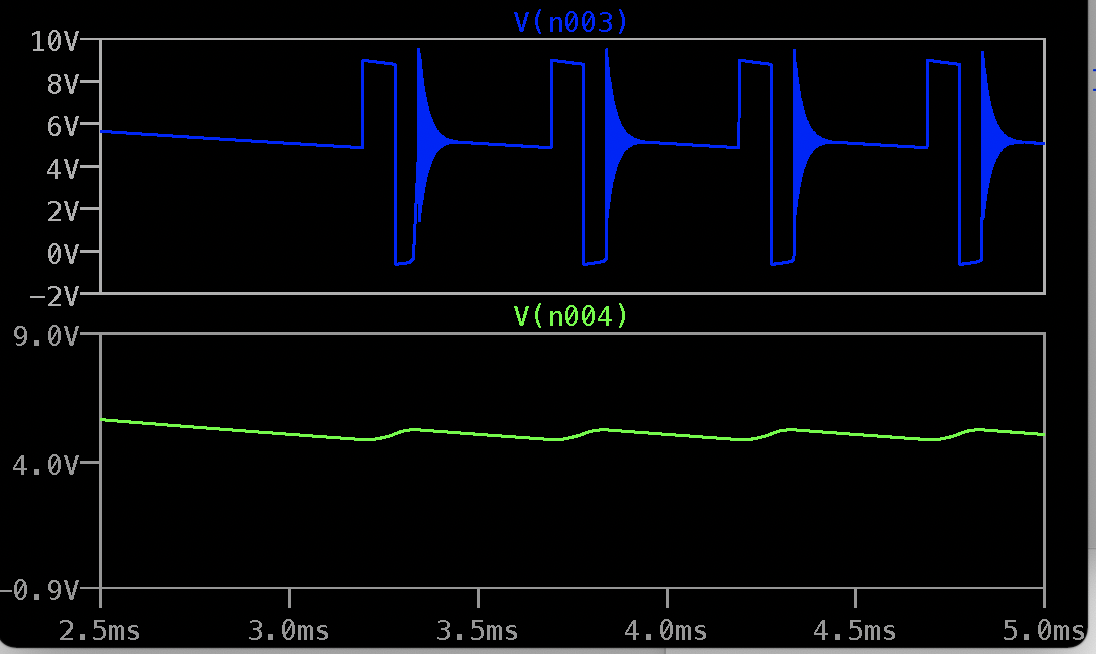
Figure 5 - Simulated results (MOSFET) ): blue curve – voltage on switch transistor drain, green curve- output voltage
5. Measured results
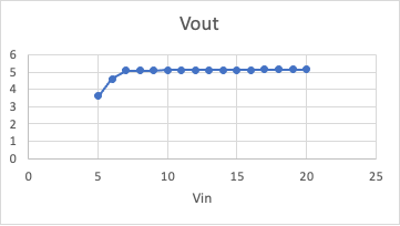
Figure 5 – Measured results (BJT with 200 mA current to load)
The output voltage stability is pretty good and the converter efficiency is around 75%.

Figure 6 – Measured results (MOSFET with 500 mA current to load)
In this version, the current capability is much higher due to the use of the high-power MOSFET. The stability remains excellent and the efficiency is above 80%.
Also, the voltage stability has been measured versus the output current changing the load resistor.
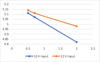
Figure 7 – Measured results (MOSFET with variable current to load)
6. Conclusion
Very good results have been obtained with a buck-converter based on recycled discrete components.
7. References
1. https://en.wikipedia.org/wiki/Buck_converter
2. https://www.analog.com/en/design-center/design-tools-and-calculators/ltspice-simulator.html